How to Choose the Right SMT Components?

Time:2026-11-02 Author:Sienna
0%

Choosing the right SMT Components is a practical engineering decision, not a catalog exercise. A resistor may fit the footprint yet drift beyond tolerance under heat. A connector may meet current needs but fail the required mating-cycle target. Small choices can affect assembly yield, product reliability, and long-term supply.

Market growth makes careful selection more important. The Semiconductor Industry Association, citing World Semiconductor Trade Statistics, reported worldwide semiconductor sales of $627.6 billion in 2024, up 19.1% from 2023. That figure describes the semiconductor market, not the entire SMT component sector, but it shows the scale and pace of change around electronic parts. Product teams should check lifecycle status, datasheet limits, package dimensions, availability, and approved alternates before release. Details matter.

The strongest selection process connects component specifications to real operating conditions: board space, thermal load, vibration, soldering profile, and expected service life. It also records why each part was chosen, so later substitutions can be assessed rather than guessed. A useful reminder comes from John Neuffer, president and CEO of the Semiconductor Industry Association: market figures are not component-level design guidance. His organization’s published data is valuable context, but it does not replace datasheets or qualification testing.

One limitation matters here: I cannot verify a verbatim quotation from an SMT Components specialist without a source. Supplying one as if authentic would weaken the reliability of this introduction.
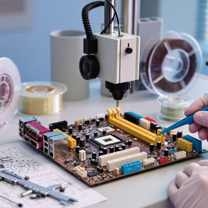
How to Choose the Right SMT Components?

Define the Role and Operating Conditions of Each SMT Component

Choosing the right SMT component starts with a clear job description. What must it sense, control, filter, or connect? A resistor used for current limiting faces different demands from one in a precision divider. Write down the expected signal, current, voltage, and response before comparing parts. Small details matter.

Next, map the operating conditions around the component. Estimate the board’s temperature range, heat from nearby parts, vibration, humidity, and available space. Check each part’s rated voltage, power, tolerance, and temperature range in its datasheet. Leave practical margin rather than designing right at a limit. For example, a resistor beside a warm power device may need more power capacity than its circuit calculation alone suggests. Package size also affects heat dissipation and assembly reliability.

Consider the whole board, not just the schematic. A capacitor may meet its nominal value but behave differently under applied voltage or temperature. A connector may fit the footprint yet be awkward to inspect or rework. This is easy to miss. I would also revisit assumptions after a prototype test; estimated temperatures and real measurements can disagree. Documenting why each component was chosen makes later substitutions safer and troubleshooting less dependent on memory.

Match Component Specifications to Electrical and Thermal Requirements

Choosing SMT components starts with the circuit’s real electrical demands, not just the values on its schematic. Check operating voltage, peak current, signal frequency, and expected transients. A capacitor rated just above the nominal voltage may lose effective capacitance under bias. Leave margin, and verify the specification at the conditions your board will actually face.

Heat matters. Estimate power dissipation from current and resistance, then compare it with the component’s thermal limits. A resistor carrying 0.2 watts on a crowded board may run hotter than its rating suggests if nearby parts restrict airflow. Package size, copper area, and neighboring heat sources all affect temperature. A datasheet’s test conditions may not match your layout; that detail is easy to overlook.

Measure where possible. Test a representative board under its highest expected load, and check temperatures after they stabilize. Review tolerances across the full operating range, especially for timing, sensing, and power-control circuits. A spreadsheet helps, but it cannot capture every layout effect. I have seen a comfortable paper estimate become tight on a dense board, so treat calculations as a starting point, not a guarantee.

How to Choose the Right SMT Components? — Match Component Specifications to Electrical and Thermal Requirements

Component Type Electrical Requirements to Check Thermal Requirements to Check Illustrative Selection Example Practical Verification
Chip resistor Resistance and tolerance; working-voltage limit; pulse or surge capability; noise requirements where relevant. Calculate dissipation using P = I²R or P = V²/R. Check the datasheet’s power derating curve and maximum element temperature. A 100 Ω resistor carrying 22 mA dissipates about 0.048 W. A nominal 0.1 W part may be a candidate, but its allowable power depends on ambient temperature, PCB copper, and datasheet derating. Confirm operating voltage is within the resistor’s limit and verify the expected board temperature and pulse conditions against the exact datasheet.
Multilayer ceramic capacitor (MLCC) Capacitance under operating conditions; voltage rating; dielectric type; tolerance; ripple-current and frequency behavior where applicable. Check temperature range and self-heating from ripple current. Account for capacitance changes caused by temperature, aging, and DC bias. An X7R MLCC is specified for −55°C to +125°C, with a temperature-related capacitance change of up to ±15% over that range. Its effective capacitance can fall further under DC bias. Use the manufacturer’s DC-bias and temperature curves for the chosen package and voltage rating; do not rely only on the printed nominal capacitance.
Power inductor Inductance and tolerance; saturation current; RMS current; DCR; operating frequency; core-loss behavior. Compare both saturation-current and temperature-rise current ratings. Account for copper loss, core loss, ambient temperature, and airflow. For a design requiring 1.2 A RMS, select an inductor whose RMS current rating supports that current at the actual board conditions and whose saturation current exceeds the maximum peak current. Check how the datasheet defines each current rating: saturation may be tied to a specified inductance drop, while thermal rating may use a specified temperature rise.
Schottky rectifier Reverse-voltage rating; average and peak forward current; forward voltage; reverse leakage; surge-current capability. Estimate conduction loss using P ≈ IF × VF, then check junction temperature using the appropriate thermal resistance and PCB layout. At 1 A and a forward voltage of 0.45 V at the relevant operating condition, conduction loss is approximately 0.45 W. The actual forward voltage varies with current and temperature. Verify junction temperature under worst-case ambient and switching conditions. Thermal resistance depends on package, copper area, and board construction.
MOSFET Drain-source voltage; continuous and pulsed current; gate-drive voltage; on-resistance at the actual gate voltage; switching charge and frequency. Include conduction, switching, and transient losses. Use the datasheet’s thermal data and safe operating area; check junction-temperature limits. At 5 A with an on-resistance of 20 mΩ at the applied gate voltage, idealized conduction loss is about 0.5 W (P = I²R), before switching and other losses. Confirm that on-resistance is specified at the available gate voltage and that the estimated junction temperature remains within limits on the intended PCB.
LED Forward current; forward-voltage range; reverse-voltage limit; brightness and color requirements; pulse-current limits. Check power dissipation, maximum junction temperature, and any current derating with temperature. Provide suitable heat spreading for higher-power LEDs. For a 20 mA indicator LED with a 2.0 V forward voltage, electrical dissipation is approximately 40 mW. Use a current-limiting driver or resistor and confirm the LED’s specified limits. Design for the maximum supply voltage and minimum forward voltage when sizing a series resistor; verify brightness and temperature in the finished assembly.

Selection note: Values shown are illustrative, not universal component ratings. Confirm all limits, test conditions, derating curves, and thermal data in the exact component datasheet, and validate critical designs on the assembled PCB.

Choose Suitable Packages for Board Space and Assembly Limits

Choosing an SMT package starts with the board’s usable area, not just the component’s body dimensions. Check the recommended footprint, courtyard, and nearby keep-out zones. A tiny resistor may fit between two traces on screen, yet leave too little room for reliable placement. Small parts look efficient. They can also make inspection and rework harder.

Assembly limits matter just as much. Fine-pitch leads need accurate pad geometry and consistent solder paste; a small alignment error can create bridges. For bottom-terminated packages, solder joints are hidden beneath the part, so inspection methods must suit the package. Ask the assembly team what placement accuracy, stencil thickness, and inspection process they can support. These details vary between production lines. A design that works well on one line may need adjustment on another.

Balance density against heat, electrical needs, and repair access. A larger package often offers more room for inspection and rework, but it can crowd connectors or reduce routing space. I have seen compact layouts look elegant in CAD and feel frustrating during assembly. That is an easy trade-off to underestimate. Before locking the footprint, review the actual package drawing and run a placement check with neighboring parts, tooling clearance, and the board edge included. A short review now can prevent awkward surprises later.

Check Availability, Reliability, and Compatibility with the PCB Design

Before approving an SMT component, check whether suppliers can meet your required quantity and lead time. A low unit price means little if stock is split across lots or delivery dates keep shifting. Ask about lifecycle status, minimum order quantities, and replenishment windows. Record an acceptable alternative when possible. Availability changes.

Reliability depends on more than a headline rating. Review the datasheet’s operating temperature, voltage derating, moisture sensitivity, and expected service conditions. For critical assemblies, request traceability documents and inspect incoming parts for damaged reels or inconsistent markings. These checks reduce risk, but they cannot replace a clear qualification plan.

Check PCB compatibility at both schematic and physical levels. Confirm footprint dimensions, pin pitch, polarity, land pattern, and soldering profile against the board files and assembly process. Then review component height, courtyard clearance, heat dissipation, and nearby parts. A package may fit the pads yet block a connector or trap heat. Leave room for tolerance. Teams sometimes trust library footprints without checking package drawings, and that shortcut can create rework. A small prototype run helps: inspect solder joints and measure key signals before committing to volume.

Validate Component Selections Through Design Review and Prototype Testing

How to Choose the Right SMT Components?

A component may match the schematic and still cause trouble on the board. During design review, compare each part’s package, pinout, electrical limits, and footprint against the manufacturer’s documented specifications. Check capacitor voltage ratings under real operating conditions, not just nominal values. Confirm polarity marks are visible and consistent across the schematic, layout, and assembly files. Small details matter.

Review the bill of materials alongside the PCB layout. Look for tight clearances, thermal exposure, and parts that may be difficult to place or inspect. Confirm that alternate components share compatible footprints and meet the same functional requirements. A second reviewer can catch a reversed pin number or a tolerance assumption that seemed obvious to the original designer. Yet reviews have blind spots; a tidy checklist cannot reveal every production issue.

Build a small prototype run before approving the design. Inspect solder joints under magnification, then test the board across its expected voltage and temperature range. Record startup behavior, current draw, and any component heating. If a part runs hotter than expected, revisit its rating and nearby copper area. Then measure again. Prototype results may not represent every production variation, but they expose practical problems early. Keep the test conditions and revisions documented so later changes can be compared fairly.

FAQS

What should I define before choosing an SMT component?

Write down its job, expected signal, current, voltage, and response time. A current-limiting resistor has different demands from a precision divider.

Why should a component have operating margin?

Ratings should cover real voltage, power, and temperature conditions, not just nominal values. Leave room for peaks and nearby heat. Exact limits can be misleading.

How can I estimate whether a component will run too hot?

Estimate power dissipation, then consider package size, copper area, airflow, and nearby heat sources. A resistor beside a warm power device may need more capacity.

Can a capacitor’s listed value stay constant in a circuit?

Not always. Applied voltage and temperature can reduce effective capacitance. Check its specifications under the conditions your board will face.

What should I check when selecting an SMT package?

Review the recommended footprint, courtyard, keep-out zones, and nearby parts. A tiny component may fit on screen but leave too little placement room.

Why do assembly limits affect package choice?

Fine-pitch parts need accurate pads and consistent solder paste. Hidden solder joints may also require a suitable inspection method. Ask what the assembly line can support.

How can I confirm thermal calculations on a real board?

Test a representative board under its highest expected load. Measure temperatures after they stabilize. Paper estimates are only a starting point.

Why document component choices?

Record the reason for each selection and revisit assumptions after prototype testing. Measured temperatures may differ from estimates. I would not rely on memory alone.

Conclusion

Choosing the right Smt Components starts with understanding the purpose of each part and the conditions it will face, including operating temperature, voltage, current, and environmental exposure. Compare component specifications with the board’s electrical and thermal requirements, allowing suitable margins to support stable performance. Package selection also matters: components must fit the available board space and remain compatible with the assembly process and its placement limits.

Before finalizing the design, check that selected parts are available, reliable, and compatible with the PCB layout, footprints, and other components. A careful design review can reveal mismatches or practical assembly concerns early. Prototype testing then helps confirm that the chosen components perform as expected under realistic conditions. By combining clear requirements, specification checks, package planning, and validation, designers can make informed selections and reduce avoidable changes during production.


Sienna

Sienna

Sienna is a skilled marketing professional with a deep expertise in our company’s core products and services. With a passion for innovation and detail, she plays a pivotal role in crafting insightful blog posts that not only highlight the unique features of our offerings but also provide valuable......